When you have a circuit that contains multiple resistors, it typically makes it easier to analyze the circuit if you can reduce the diagram down to a simplified model. One way of doing this is to find an equivalent resistance of the resistors in question, which would allow you to model them as fewer (ideally one) resistors.
To do this you must recognize a resistor -- depicted as a "sawtooth" line, having a resistance with a unit called "Ohms" (symbolized as Omega) -- and when resistors are in series or in parallel. Resistors are in series when they are attached end-to-end; that is, a "piece" of current flows through one before it reaches another. Resistors are in parallel when the "beginnings" are all connected to each other, as are the "ends"; or another way to think about it, the current is passing through them all simultaneously. The video shows examples of this.
These groups of resistors can be modelled as a single equivalent resistor by using the following principles:
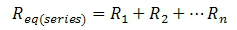
- Resistors in series are simply added together. The equivalent resistance for n quantity of resistors in series is:
- Resistors in parallel are slightly trickier; the equivalent resistance is the inverse of the sum of the inverses of the individual resistances. That's a mouthful! So check out the following equation for the equivalent resistance of n resistors in parallel:

If several resistors are all in series or all in parallel, the problems are easy. However, often you will have a more complex circuit where some resistors are in parallel and others are in series. In this case you will have to group together and pick away at the problem step by step. For example, if you have a circuit where two resistors are in series with each other, and parallel to a third resistor, you can find the equivalent resistance of the two series resistors first, and then find the equivalent resistor of that value in parallel with the third resistor. See the practice problems if that is unclear.
TIP: Watch out for the short circuit. If there is any point on the circuit where a plain "wire" completes the circuit, everything on the far side of the short (relative to the source) is not part of the analysis. Watch the video lesson for an example of this. This is something the FE people will do to try to trick you!
TIP: One think you'll notice -- and this is an excellent "dummy check" of your work, and a possible way to eliminate bogus answers on the multiple-choice FE -- is that resistors in series always lead to an increased equivalent resistance, while resistors in parallel have an equivalent resistance that is lower than any of the individual resistors. Series --> more, Parallel --> less.
This is useful when using Ohm's Law to find other parameters of a circuit. The process for capacitors and inductors is very similar. If you can grasp this concept you can get those down and analyze circuits with even more components.
PRACTICE PROBLEMS: These circuit diagrams are kind of hard to draw on the computer, so I made some problems by hand. Below are PDF files; one with example problems, another with solutions.
Please let me know if you see any errors or points that could use clarification. Hope this helps!
No comments:
Post a Comment